 Mingri Electric
1 / 1
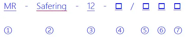
| No. | Description |
| 1 | Manufacturer Code |
| 2 | Model Type |
| 3 | Rated Voltage: 12 (12KV); 24 (24KV) |
| 4 | Cabinet Type: C (Load Switch); F (Fuses Switchgear); V (Vacuum Circuit Breaker); M (Measuring); SV/SL (Bus Sectionalizing); PT (PT Cabinet) |
| 5 | Rated Current: 630 (630A); 1250 (1250A) |
| 6 | Expansion Type: I (Left); D (Right); ID (Both Sides); Blank (Extendable) |
| 7 | Cable Entry/Exit: L (Left); R (Right); LR (Both); Blank (Front) |
| Code | Description | Code | Description |
| C | Standard Single-Bushing Load Switch | - | Top Busbar Bushing |
| F | Load Switch-Fuse Combination | SL | Bus Coupler Unit |
| V | Circuit Breaker Unit | M | Metering Unit |
| D | Cable Incoming Unit (Non-Switch) | PT | PT Unit |
| + | Busbar Side Bushing | 1K2(4) | Load Switch Unit with Double Bushings |
| SF6 Gas Data | Environmental Conditions | ||
| Gas Pressure | 1.4 BAR (Absolute at 20℃) | Max Temperature | 40℃ |
| Leakage Rate | ≤0.2% per year | Min Temperature | -40℃ |
| Protection Level | IP67 | Max Humidity | ≤95% |
| Chamber Thickness | 3.0mm (Stainless Steel) | Altitude | ≤2000 meters |
| Busbars & Components | Color Standards | ||
| Switchgear Busbar | 400mm² Cu | Front Panel | RAL7012 |
| Switchgear Grounding | 150mm² Cu | Side & Cable Covers | RAL7035 |
| Compliant Standards | |||||
| GB/T11022 | GB3906 | GB1985 | GB3309 | IEC60129 | IEC60298 |
| GB16926 | GB38041 | GB1984 | IEC60056 | IEC60265 | IEC60420 |
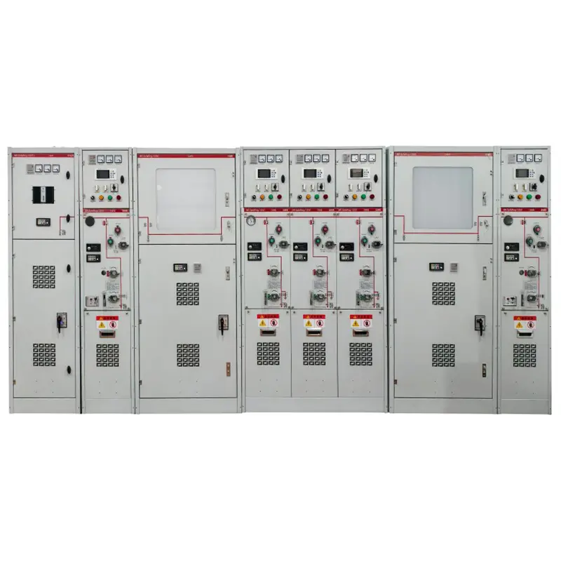
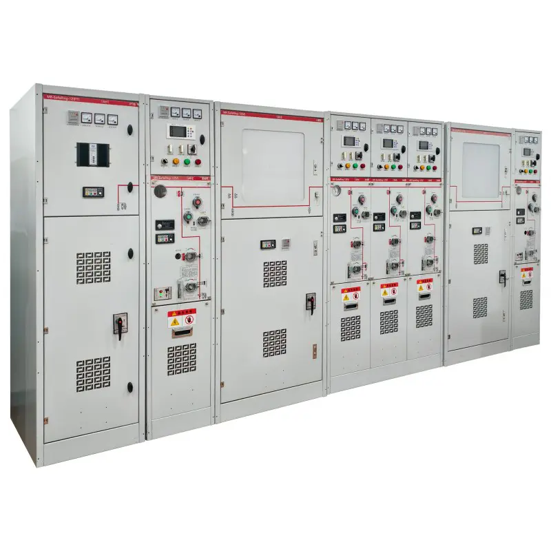
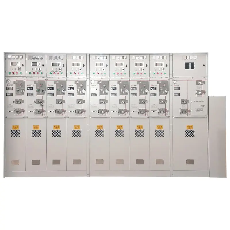
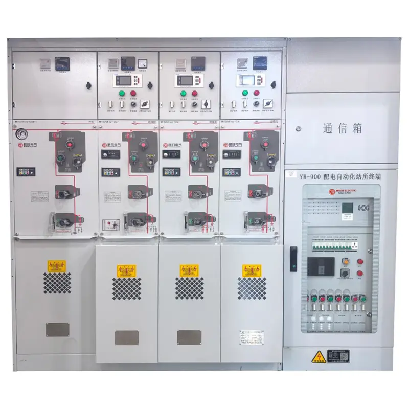
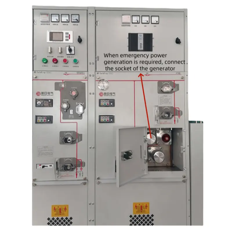
| Parameter | Unit | C Module | F Module | V Module | CB Module |
| Rated Voltage | kV | 12 | 12 | 12 | 12 |
| Rated Frequency | Hz | 50 | 50 | 50 | 50 |
| Withstand Voltage (Phase-to-Phase) | kV | 42/48 | 42/48 | 42/48 | 42/48 |
| Lightning Impulse Withstand | kV | 75/85 | 75/85 | 75/85 | 75/85 |
| Rated Current | A | 630 | - | 630 | 1250/630 |
| Short-circuit Making Current (Peak) | A | 50 | 80 | - | - |
| Short-time Withstand Current | kA/3s | 20 | - | - | - |
| Short-circuit Breaking Current | kA | - | 31.5 | 20 | 25 |
| Mechanical Life | Ops | 5000 | 3000 | 5000 | 5000 |
Note: Parameters may depend on fuse ratings.
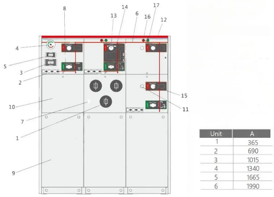
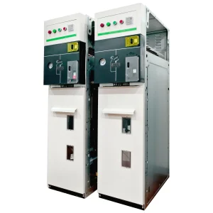
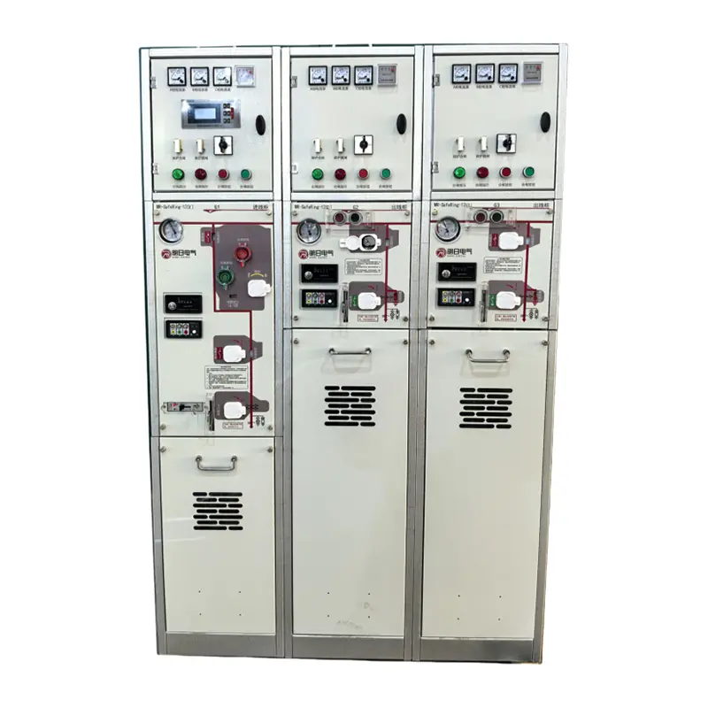
| 1. Fuse Compartment | 5. Serial Number Label | 9. Cable Compartment | 13. Load Switch Port |
| 2. Voltage Indicator | 6. Schematic Diagram | 10. RTU Compartment | 14. Earthing Port |
| 3. Fault Indicator | 7. Fuse Blow Indicator | 11. Key Lock | 15. Disconnector Port |
| 4. Pressure Indicator | 8. Padlock Device | 12. Breaker Port | 16. Trip/17. Close Button |