 Mingri Electric
1 / 3
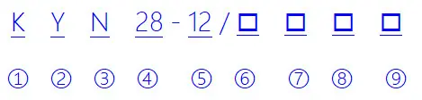
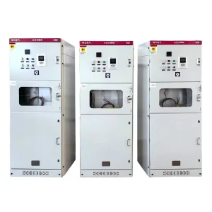
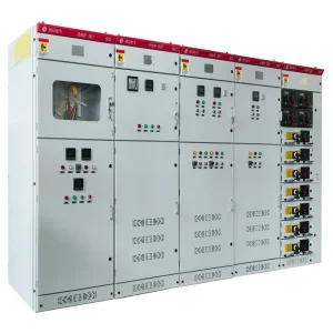
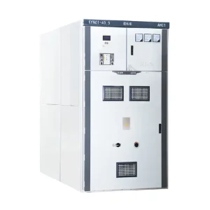
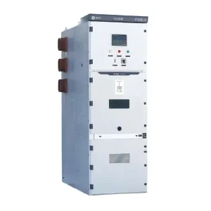
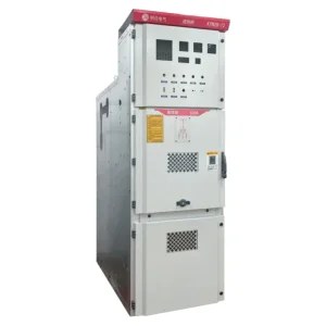
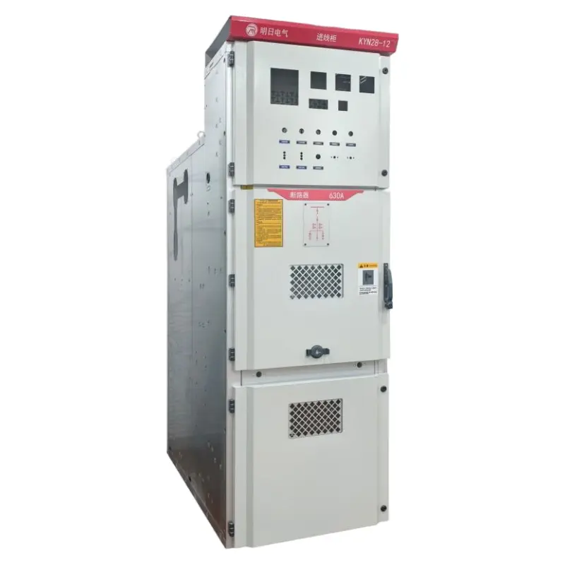
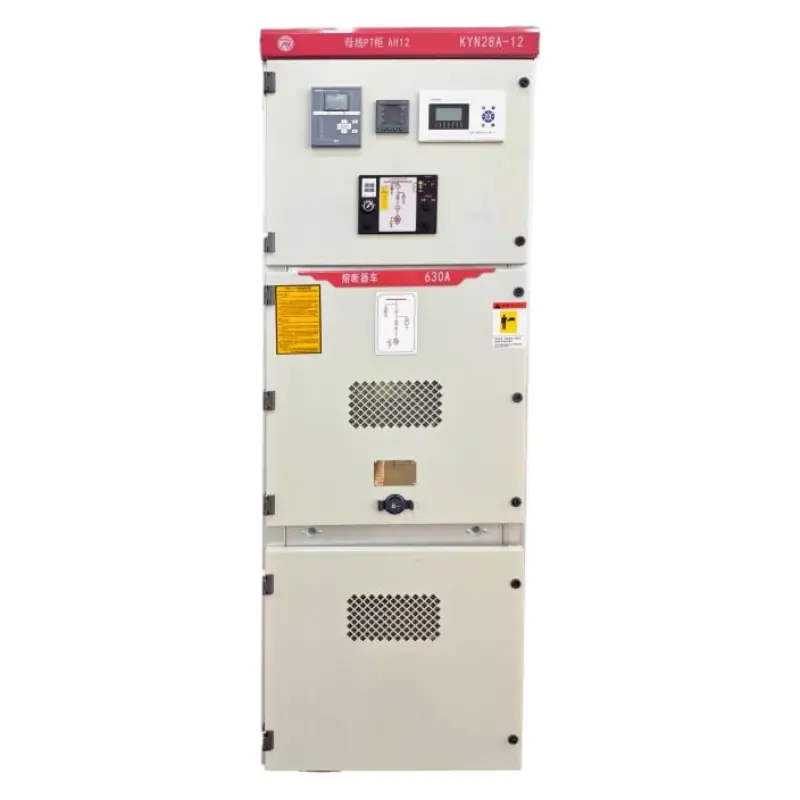
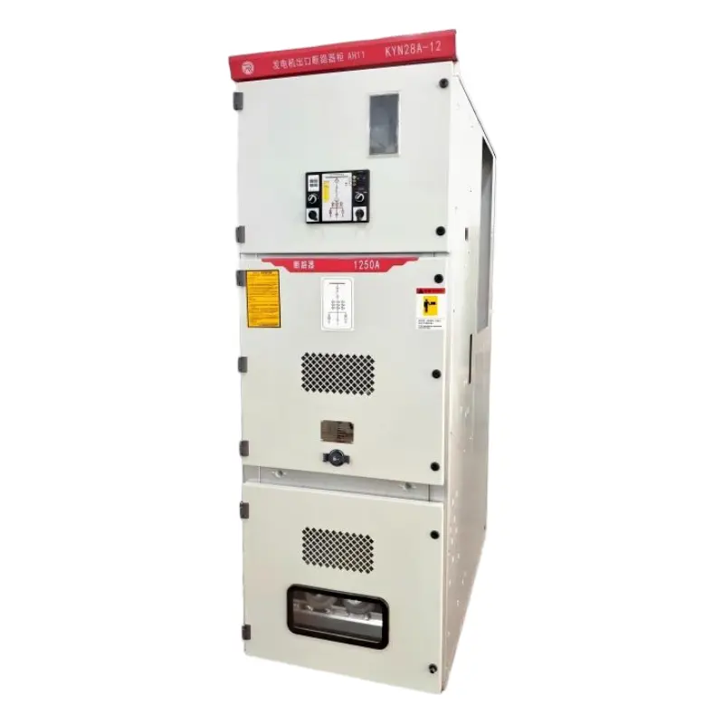
| 1 | Armored Withdrawable Metal-Clad Switchgear |
| 2 | Withdrawable Type |
| 3 | Usage Conditions: (Indoor) |
| 4 | Design Serial Number |
| 5 | Rated Voltage (kV) |
| 6 | Main Circuit Diagram No. |
| 7 | Operating Mechanism Code, D: Electromagnetic; T: Spring |
| 8 | Rated Current (A) |
| 9 | Rated Short-Circuit Breaking Current (kA) |
| Item | Unit | Value |
|---|---|---|
| Rated Voltage | kV | 12 |
| Rated Frequency | Hz | 50 |
| Main Bus Rated Current | A | 630, 1250, 1600, 2000, 2500, 3150 |
| Rated Current | A | 630, 1250, 1600, 2000, 2500, 3150 |
| Earthed Circuit Rated Short-Time Withstand Current(2s) | kA | 13.9, 17.4, 21.8, 27.4, 34.8 |
| Main Circuit Rated Short-Time Withstand Current (4s) | kA | 16, 20, 25, 31.5, 40 |
| Rated Peak Withstand Current(Peak) | kA | 40, 50, 63, 80, 100 |
| Rated Short-Circuit Breaking Current | kA | 25, 31.5, 40 |
| Rated Insulation Level (1min Power Frequency) | kV | Phase-to-ground: 42; Breaking: 48 |
| Rated Insulation Level (Lightning Impulse) | kV | Phase-to-ground: 75; Breaking: 48 |
| Protection Class | Enclosure: IP4X |
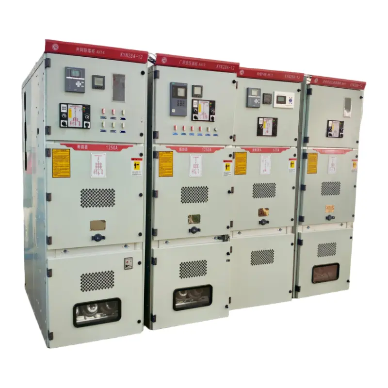
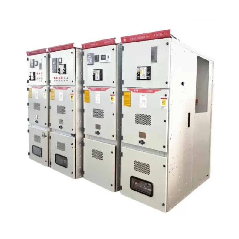
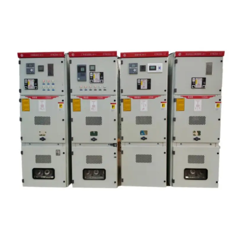
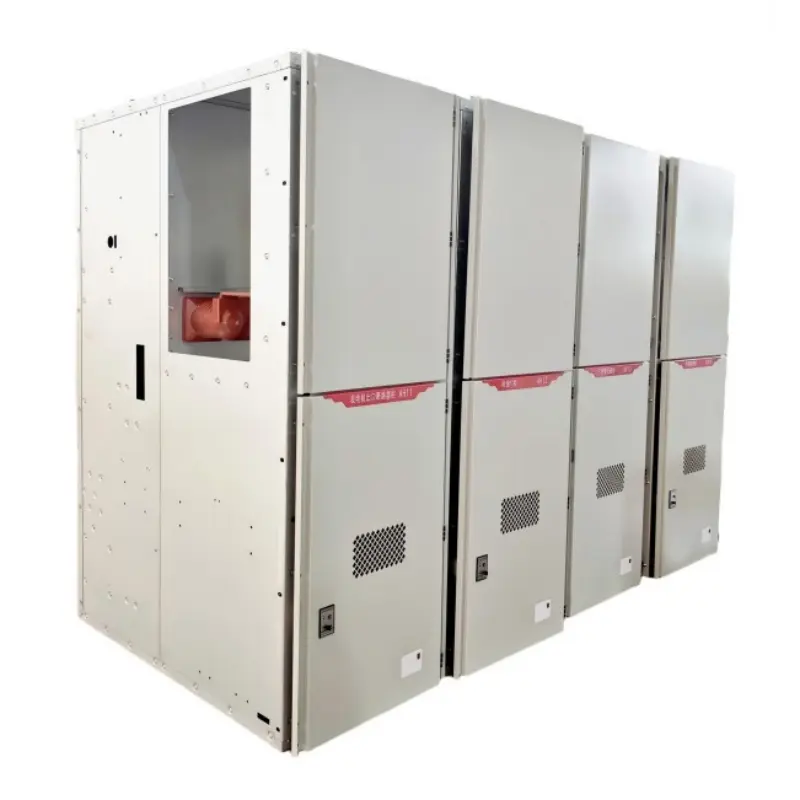
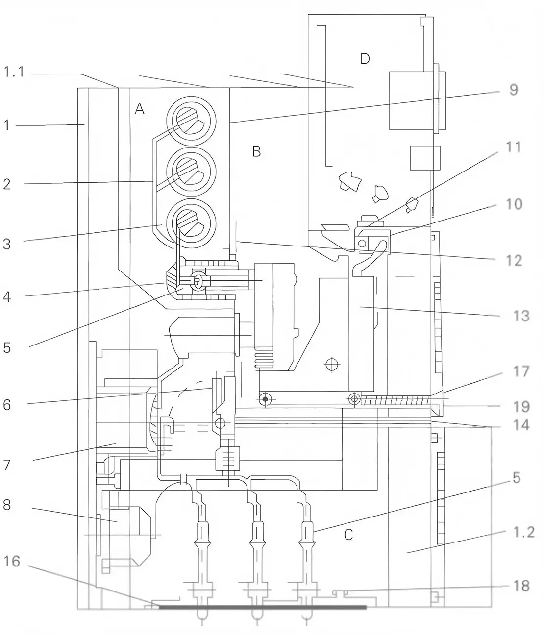
Fig.1: KYN28-12 Feeder Switchgear Cross-Sectional Diagram
| A. Busbar Compartment | 3. Main Busbar | 9. Removable Partition | 15. Cable Sealing End |
| B. Circuit Breaker Compartment | 4. Fixed Contact Assembly | 10. Secondary Plug | 16. Base Plate |
| C. Cable Compartment | 5. Spring-Loaded Contact | 11. Auxiliary Switch | 17. Lead Screw Mechanism |
| D. Instrument Compartment | 6. Earthing Switch | 12. Movable Shutter | 18. Earthing Main Busbar |
| 1. Enclosure (Relief Panel/Cover) | 7. Current Transformer (CT) | 13. Withdrawable Trolley | 19. Removable Horizontal Partition |
| 2. Branch Busbar | 8. Voltage Transformer (VT) | 14. Earthing Switch Mechanism |
Product operating site and special requirements: